Version 1.3, 20080407
In my opinion, using a passive network tap (PNT) is essential to security and compliance.
Not only is having one handy to quickly plug into the network path of a suspicious host or server, it is absolutely necessary to have one on the primary Internet path.
You can spend thousands of dollars for firewalls, IDS's, and IPS's, but what guarantee do you have that they work unless you verify every packet.
There are two basic kinds of PNT's; the cheap and the expensive.
The cheap PNT can be homemade for under $20.
The expensive PNT costs anywhere from $1,000 upwards.
In this article, I will outline construction and use of the cheap PNT. My configuration examples will be specific to Debian Linux, but I have included links regarding use with other “nix” distributions as well.
NOTE: Remember; this tap is for a 10/100 ethernet connection only. If you need to monitor or protect a Gigabit link, consider a commercial tap or try my homebrew version.
Caveat:
This ethernet tap is not a substitute for a tap that uses electronics to sample the network traffic. It should never be placed inline with a critical, production host due to the likelihood of anywhere from 10% to %50 errors and packet loss. It should be used only for spot checks of hosts where other methods of sniffing the traffic are not convenient. In practice, it is simply a very handy gadget to carry around in your network tool bag. REPEAT: For tapping a critical, production system, consider only the best quality passive tap you can afford, and only use the “cheap” PNT when it's your only choice for as short a time as possible to avoid degrading the network unnecessarily.
But:
In my own use, where I put the tap and for how long depends on the nature of the network interface cards in the sensor itself. I have plugged them into network and internet connections and left them there with zero error rates. To get a better idea of how good the cheap PNT can work, read my paper PNT Sensor Configuration and Performance.
Surface mount box – one per network tap
Cat5E RJ45 keystone jacks – four per network tap
Cat5E network cable – about six inches per network tap
I got mine from CompuNetTech.com, which was the least expensive, highest quality source I could find. Radio Shack has excellent components also, but at a higher price.
My parts cost per tap was:
Surface Mount Box - 4 Ports - $1.99 ( 1x )
Cat5E RJ45 Keystone Jack - $1.59 ( 4x)
a scrap of Cat5E patch cable ( be sure it has four pairs – some have only two )
Total - around $8.35, plus the cost of cable if you have to buy it
This is my method. Your mileage may vary.
Insert a medium-small screwdriver blade into the slots on the sides of the mount box, one at a time, and twist slightly while pulling up on the top of the mount box to remove the cover.
Place the keystone jacks into their mounting slots with the wire punchdown blocks facing upwards. The jacks must be inserted with the front at a downward angle, then the back of the jack is snapped downward into place. Be careful to not break the thin plastic mounting bracket.
Measure the distance between the outside wire punchdowns on the outermost jacks, then add an inch. Cut a length of Cat5E cable to this length. The quick 'n' dirty method is to just lay the cable out across the wire blocks with about an inch to spare, then make the cut.
Carefully cut into the insulation of the cable a half-inch or more, so that it can be pulled back to expose the wire pairs inside ( I prefer to use thin wire snips to ensure I don't slice the wires ). Then, carefully pull the wire pairs out of the insulation.
Be sure to not disturb the wire pairs. It's critical to retain the tightness and rate of twist to avoid RF interference that could induce errors. You should have the pairs blue/blue-white, orange/orange-white, brown/brown-white, and green/green-white.
For wiring purposes, picture the jacks as HOST – Tap A – Tap B – HOST, from left to right, then use a punchdown tool to wire the jacks as follows:
Typically, the punchdown blocks on the jacks are color coded for ANSI/TIA/EIA T568a and T568b wiring. You will want to use the wiring legend as a guide. Most jacks have a tiny letter “a” or “b” next to the respective wiring legend. Also, above the Tap A/B jack connections, you will need to pull the wire pair apart just enough to punch it down on the respective color coded jack punchdown pair. Be careful when doing this to not disturb the twist of the wire pair any more than is absolutely necessary.
On the left HOST jack, punch down the orange/orange-white wires to the corresponding pins.
On the second jack “Tap A”, punch down the orange/orange-white pair of wires to the green/green-white pins.
On the right HOST jack, punch down the orange/orange-white pair to the corresponding pins.
On the left HOST jack, punch down the green/green-white pair to the corresponding pins.
On the third jack ( Tap-B ), punch down the green/green-white pair to the corresponding pins.
On the right HOST jack, punch down the green/green-white pair to the corresponding pins.
The remaining wire pairs, blue/blue-white and brown/brown-white, will not connect to the second and third jacks, but will be punched down between the left and right jacks only, forming a “straight-through” connection.
Once you're done, (A) test the wiring and (B) cut off the excess wire from the end connections
Here's a table showing the wiring:
|
Wire# |
HOST |
Tap A |
Tap B |
HOST |
|
2 |
orange |
|
|
orange |
|
1 |
orange-white |
|
|
orange-white |
|
3 |
green |
orange |
green |
green |
|
6 |
green-white |
orange-white |
green-white |
green-white |
|
8 |
brown |
|
|
brown |
|
7 |
brown-white |
|
|
brown-white |
|
4 |
blue |
|
|
blue |
|
5 |
blue-white |
|
|
blue-white |
In use, each “Tap” jack will carry only half of the network traffic. It will be the job of the system used as a sensor to combine the traffic. With Linux, this is done with a package called “ifenslave”.
Using a network test rig, follow this procedure:
Plug the remote indicator into the first HOST jack and the tester into the other HOST jack. Run the test. You should see a sequential led indication of 1-2-3-4-5-6-7-8 on the remote indicator.
Move the remote indicator plug from HOST to Tap-A. You should see the led indicators blink skip-skip-3-skip-skip-6-skip-skip.
Move the remote indicator plug from Tap-A to Tap-B. You should see the led indicators blink skip-skip-3-skip-skip-6-skip-skip.
The PNT is now ready to configure and test.
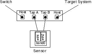
Unless you plan to administrate the sensor from the console only ( which is the most secure way to do things, by the way ), the system must have three network interfaces ( NIC's ). Typically, I use the first interface ( eth0 ) for the admin network, then the second and third NIC's ( eth1 and eth2 ) for the tap.
If you are going to put the sensor on a network, it should be a dedicated network with the highest security, that is used only by trusted security personal for systems management.
IMPORTANT:
All network ports on all active devices should be configured to the highest speed setting the link partners are capable of. This means that a NIC should be set to 100TX full-duplex on the host, and its switch port should be set to match. There are very few instances where there's an advantage to having devices running on “auto negotiate”. And, there are many reasons NOT to have NIC's and switches trying to negotiate. I've seen too many problems with “auto negotiate” settings.
I have tested my homemade PNT's successfully on both 10mb and 100mb networks. One simply has to get used to getting console/log messages about “no link”, due to the fact that each NIC on the sensor is only getting half a signal. So far, this seems to eliminate using the “cheap PNT” for sniffing a 1000mb connection. I haven't found a gigabit NIC yet that provides for setting the speed to 1000mb. I have thought about looping back the TX connections within the TAP to the bonding NIC's to fool the devices, but haven't tried that yet. If you come up with some solutions for gigabit sniffing with the PNT, let me know.
I apologize to the GUI-only sysadmins out there, but I've always been a hands-on, text-edit kind of guy. These instructions involved manually editing the necessary files themselves.
The package “ifenslave” must be installed. This kernel module and utilities permit the “bonding” of two or more NIC's, which can be used to either combine the two half-duplex flows of PNT's Tap-A and Tap-B, or even do load balancing or high-availability.
Edit the file: /etc/network/interfaces
add:
auto bond0
iface bond0 inet manual
pre-up ifconfig eth1 promisc -arp up && ifconfig eth2 promisc -arp up && ifconfig bond0 up
up ifenslave bond0 eth1 eth2
down ifenslave -d bond0 eth1 eth2
post-down ifconfig eth1 down && ifconfig eth2 down && ifconfig
bond0 down
Edit the file: /etc/modprobe.d/arch-aliases
add:
alias bond0 bonding
options bonding mode=1 miimon=100 downdelay=200 updelay=200
Once the above edits are done, reboot the system and check to see if bond0 is active.
The basic theory of operation is to insert the PNT between a system and its network connection. Then, a cable is connected between the first bonding NIC on the sensor and Tap-A on the PNT. A cable is then connected between the second bonding NIC and Tap-B on the PNT. Like so:
When using tcpdump to capture packets, the interface to specify is bond0. Likewise, bond0 would be referenced in any snort IDS configuration.
After capturing some packets, it's always a good idea to verify the integrity of the data. The total of packets captured by bond0 on the sensor should be identical to the packets received and transmitted by the NIC of the system being monitored. And, keep a close eye on the error count. If it's excessive, chances are the combination of either the sensor NIC's or either end just aren't going to work.
For an excellent example of tap usage, see Mr. Richard Bejtlich's illustrated examples:
http://taosecurity.blogspot.com/2005/12/taps-and-hubs-never-ever-mix-ive.html
http://taosecurity.blogspot.com/2005/12/taps-and-hubs-part-deux-yesterday-i.html
Richard's blog is a great reference, plus his book The Tao of Network Security Monitoring is a “must have”.
See my paper PNT Sensor Configuration and Performance for more detailed information regarding selection of network interface cards, configuring the sensor, and error rates.
Lastly, here's a photo of a finished product.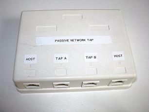
The fine reference I used: http://www.sun.com/bigadmin/content/submitted/passive_ethernet_tap.html
Snort site IDS Deployment Docs: http://www.snort.org/docs/
FreeBSD: http://seclists.org/lists/focus-ids/2003/Oct/0028.html
Revision history:
v1.3 - 20080407 Added picture, links to photos of wiring, and emphasized clean wiring
v1.2 – 20060201 Added notes on network interface card selection and error rates
v1.1 – 20051018 Correction of errors in the wiring description and network test set readings. My apologies.
Copyright © 2005,2006,2008 Mark Stingley